Using the Ceiling Mount
Install Everything Presence Pro with the ceiling mount. Follow the mounting guide and prepare your device for ceiling placement.
Everything Presence Pro comes with an optional Ceiling Mount kit, allowing you to flush mount your Everything Presence Pro into a ceiling or wall for discreet installation.
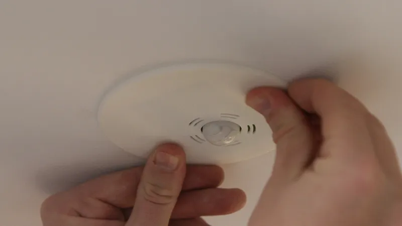
Assembly Guide
Video Guide:
https://www.youtube.com/watch?v=4TA%5FFH-euSU&pp=0gcJCYcKAYcqIYzv
Pre-requisites
- Everything Presence Pro
- Everything Presence Pro Ceiling Mount Kit
- Philips Screwdriver
- CO2 Module (optional)
- Strong fingers (not optional)
Disassembling the original enclosure
First, we need to remove the main Pro PCB from the original enclosure by removing the front face plate.
This is a little tricky since it needs to be very secure in the case of drops, but we have found the best way is to place your index finger and thumb on the top and bottom of the device, only on the front face plate:
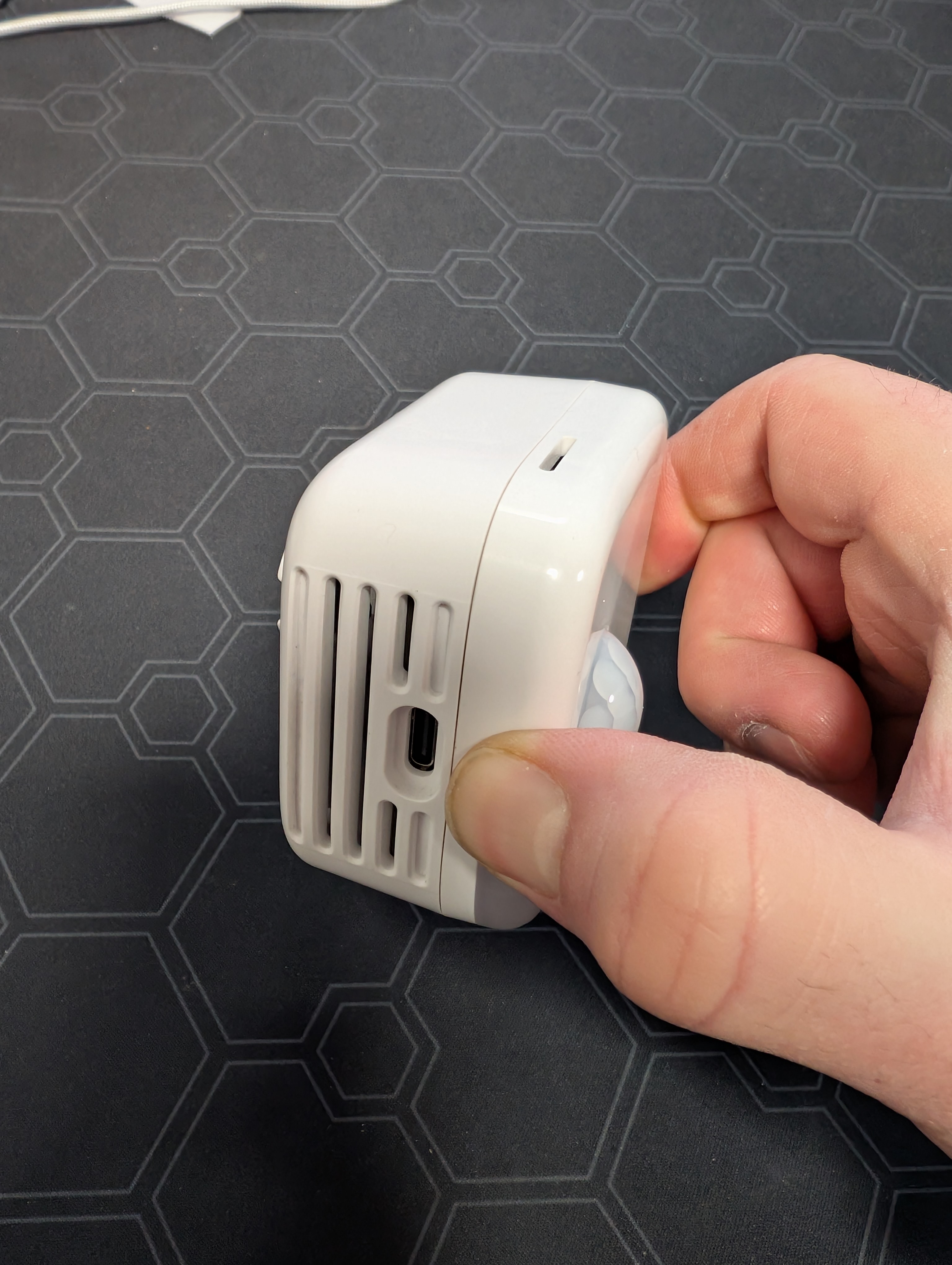
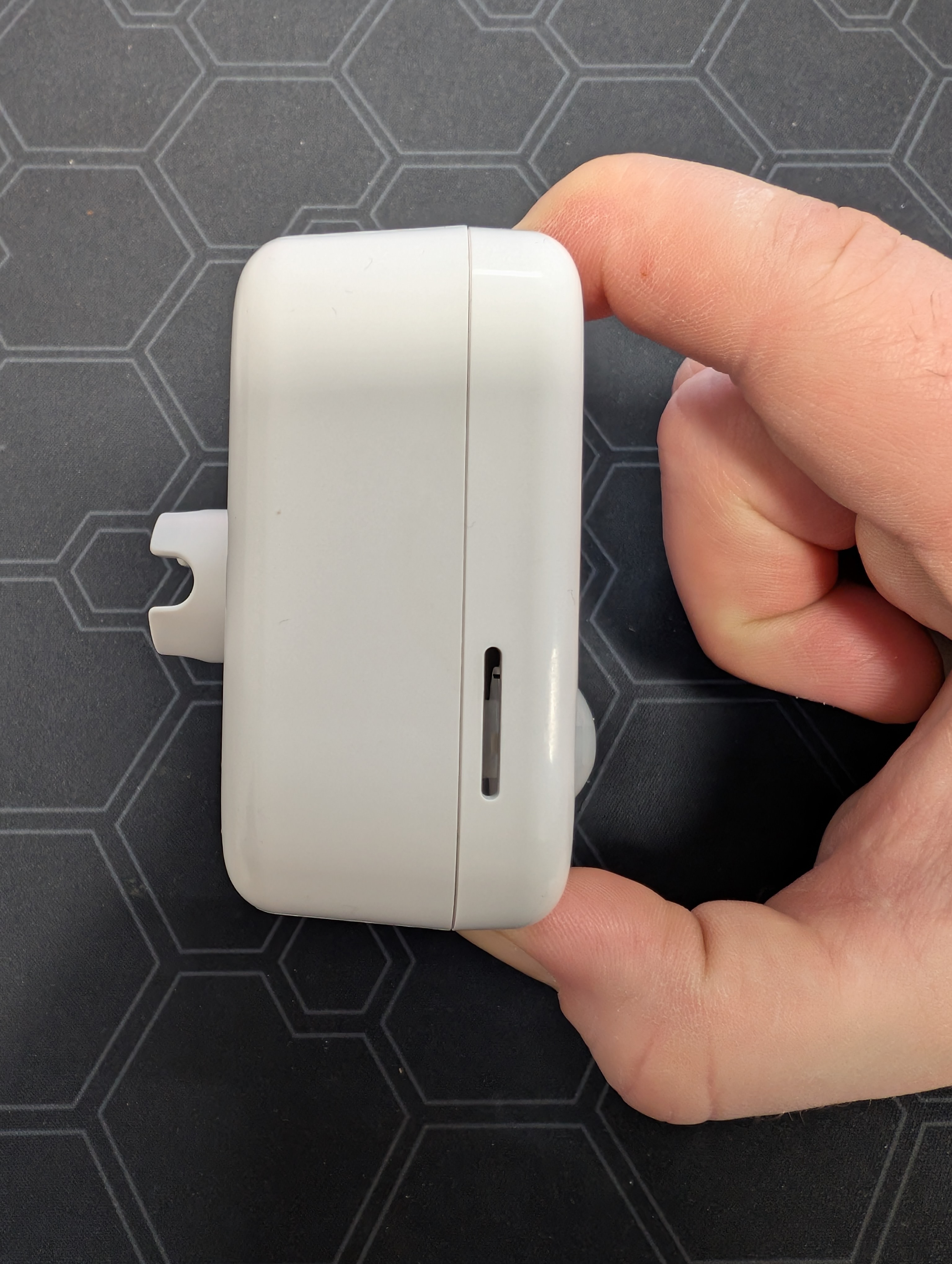
Once in this position, squeeze hard on the face plate and wiggle side to side while pulling to the front. This action will release the side clips and make it easier for the front panel to come off. It’s quite secure so does take quite a good bit of squeezing and wiggling!
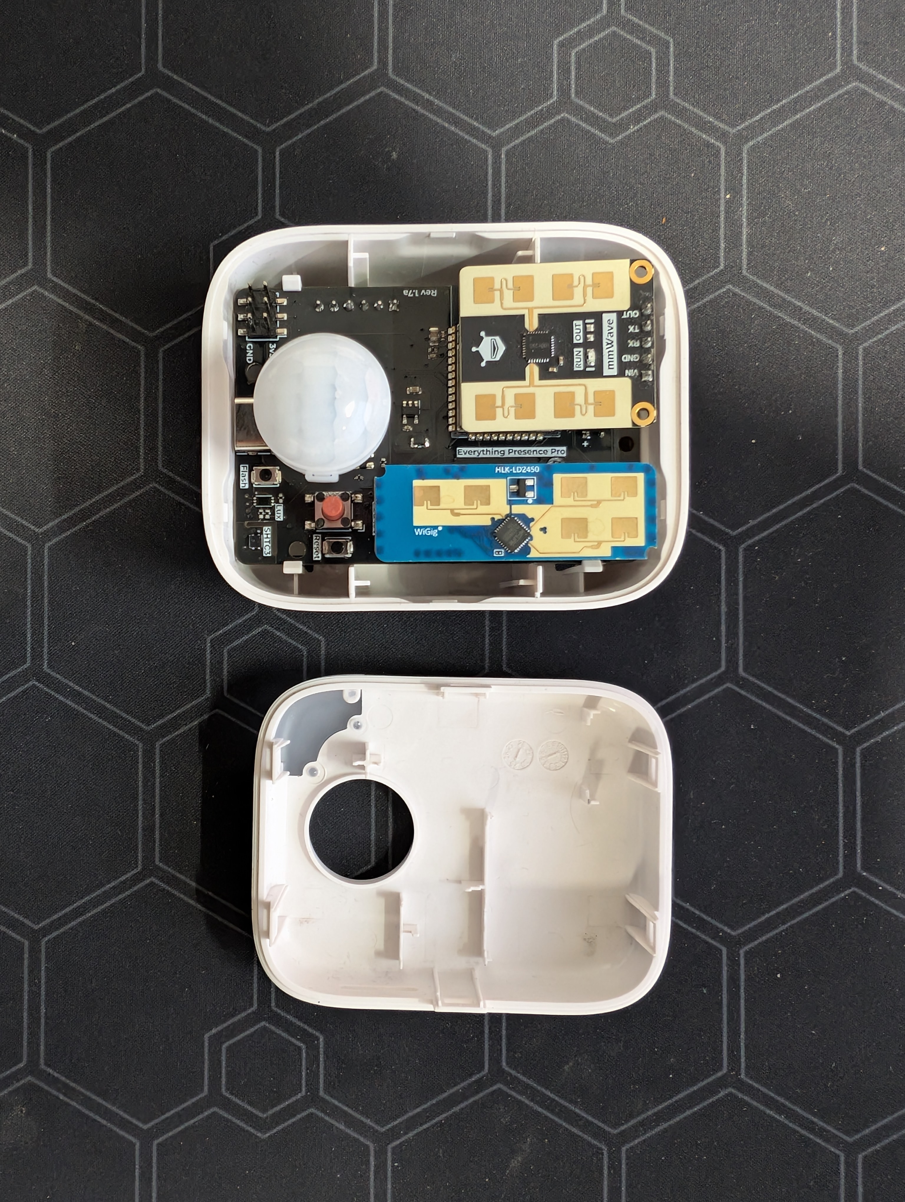
Next, carefully remove both mmWave sensors from their socket, being careful not to bend any pins. Also remove the PIR from it’s socket in the same way.
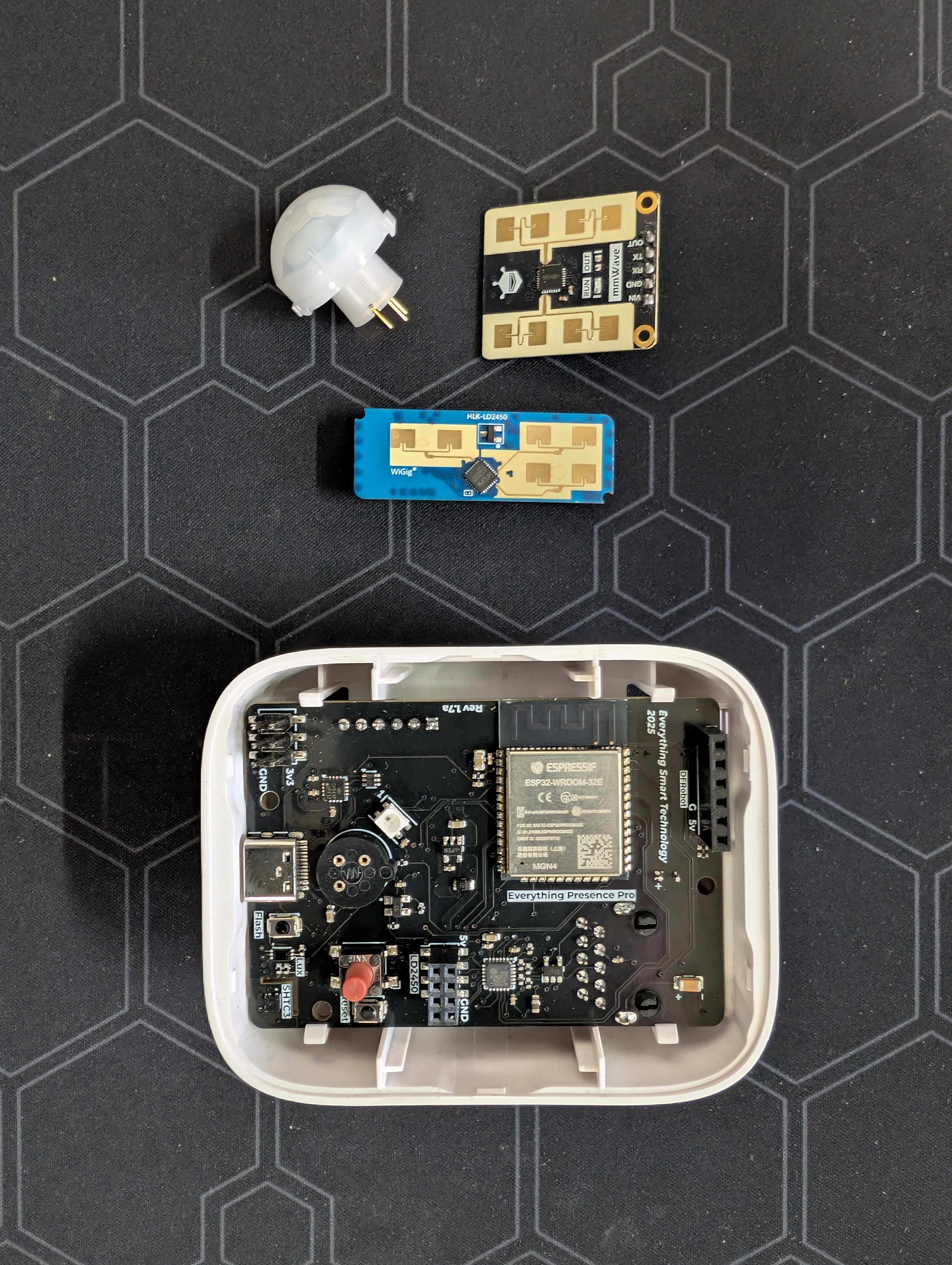
Finally we can remove the main PCB. This is held in by 4 clips, one at each corner.
The easiest way is to place your thumb between the PCB and the edge of the case at the left hand side (when the USB-C is pointing down):
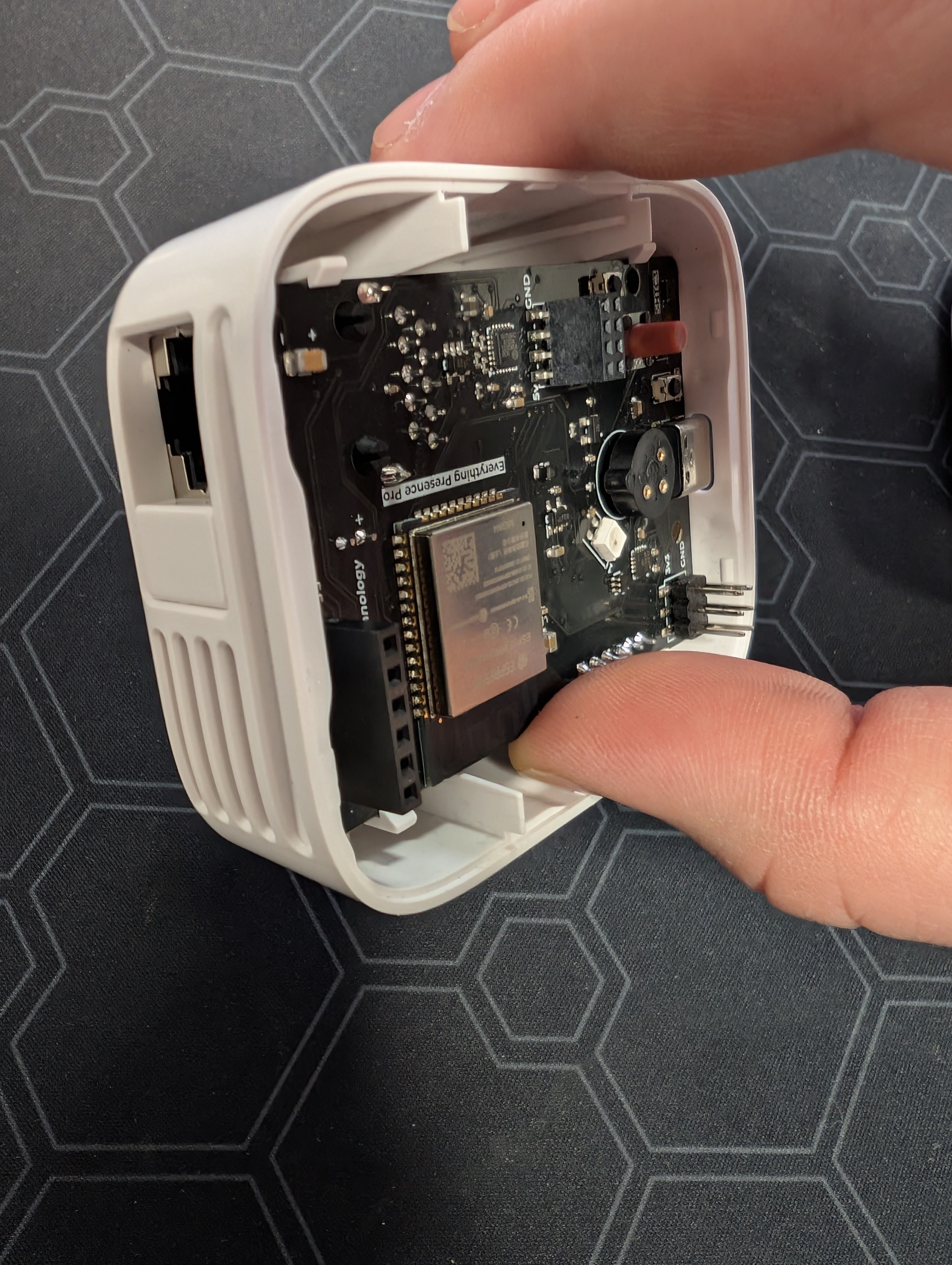
Gently press the PCB to the opposite side and lift passed the clips:
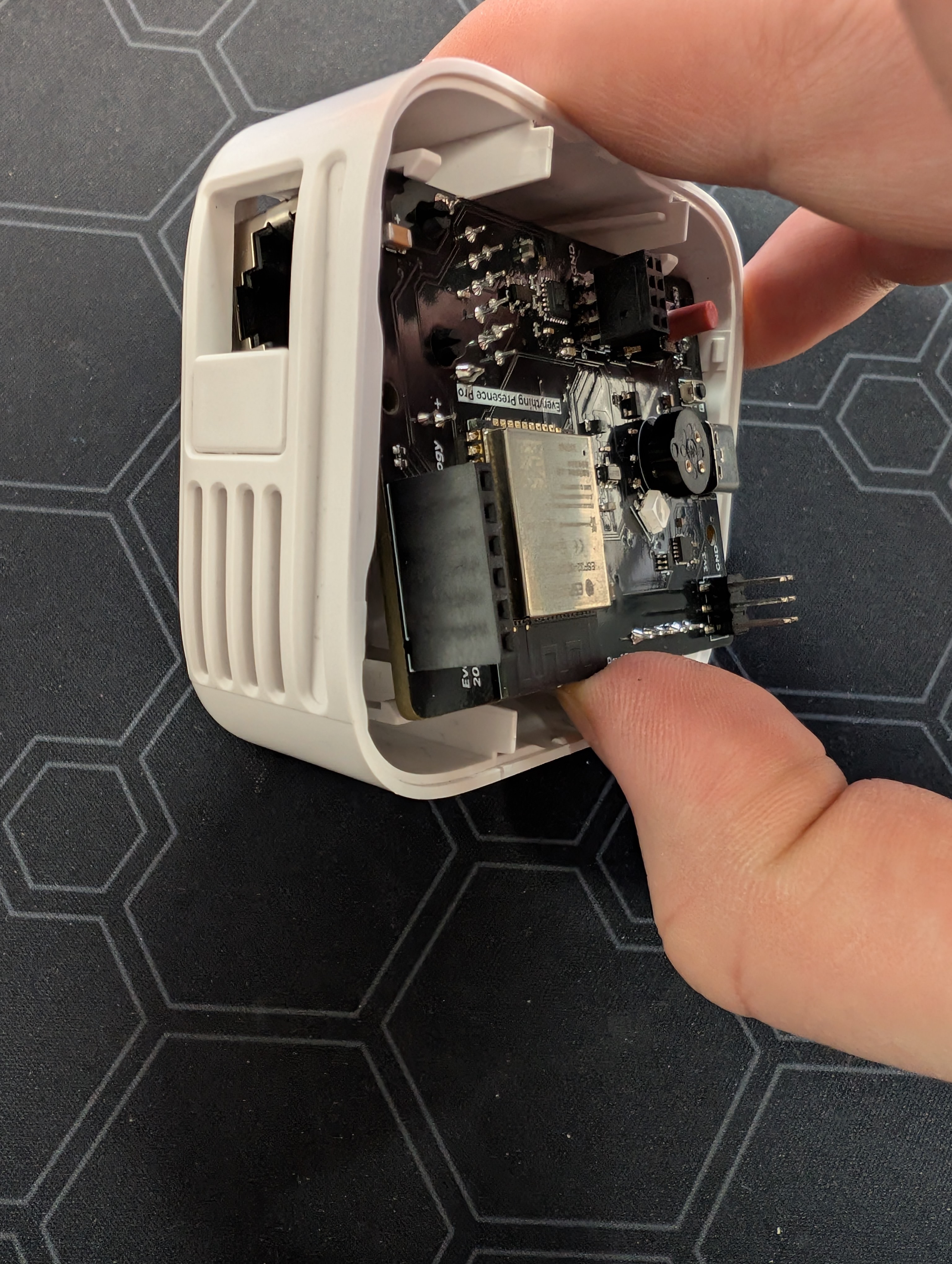
Tip
Recommend doing it from the left side as shown, as the ethernet can get jammed removing from the opposite direction.
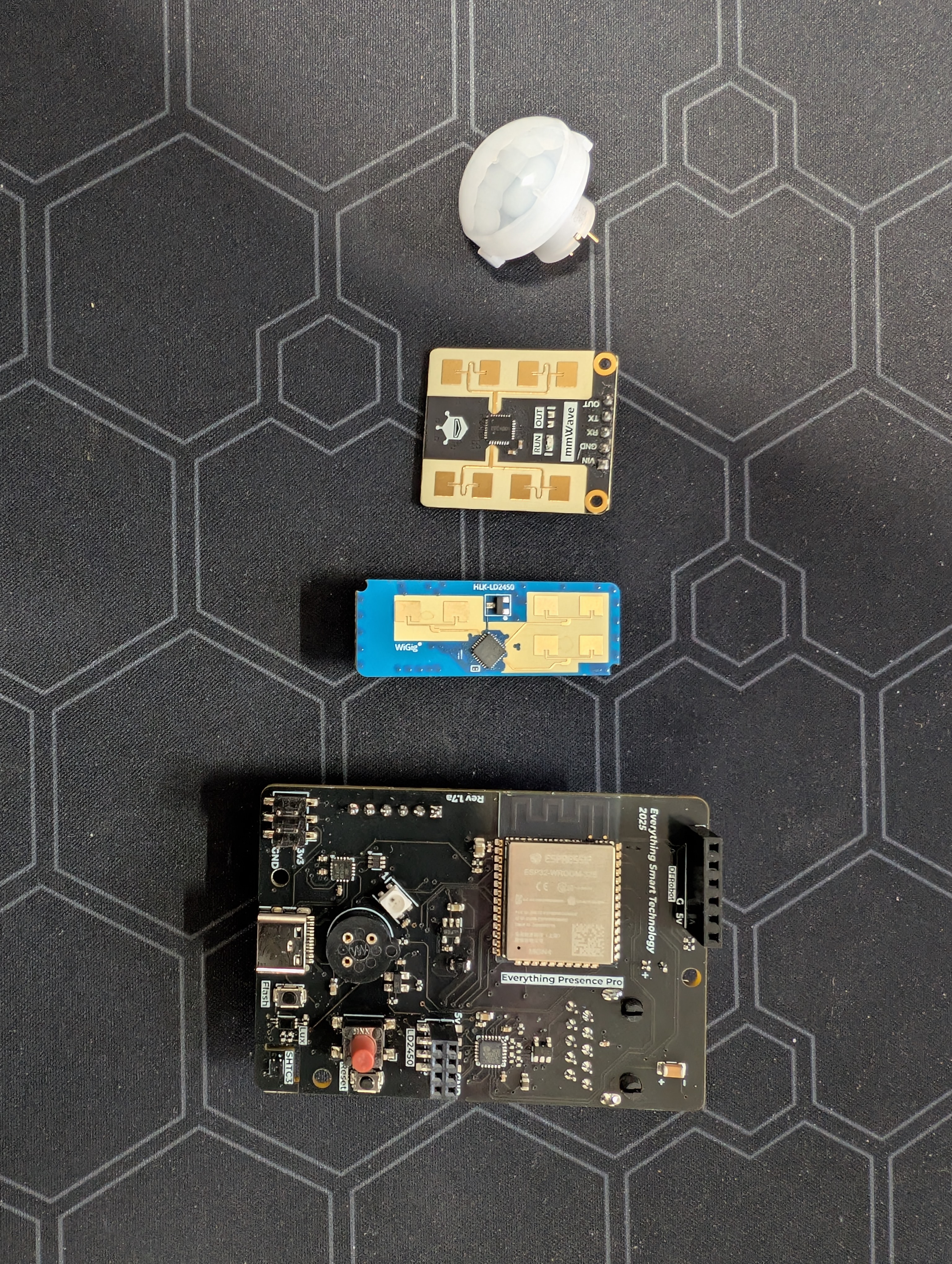
Leaving you with the main PCB, 2 x mmwave sensors and 1 x PIR:
Assembling the Ceiling Mount
In addition to the Pro components, you will need:
- 1 x Ceiling Mount Rear
- 1 x Ceiling Mount Middle
- 1 x Ceiling Mount Front
- 2 x Ceiling Mount Wings
- 2 x M3x25 “big” screws (included)
- 2 x M3x10 “medium” screws (included)
- 2 x M2x8 “little” screws (included)
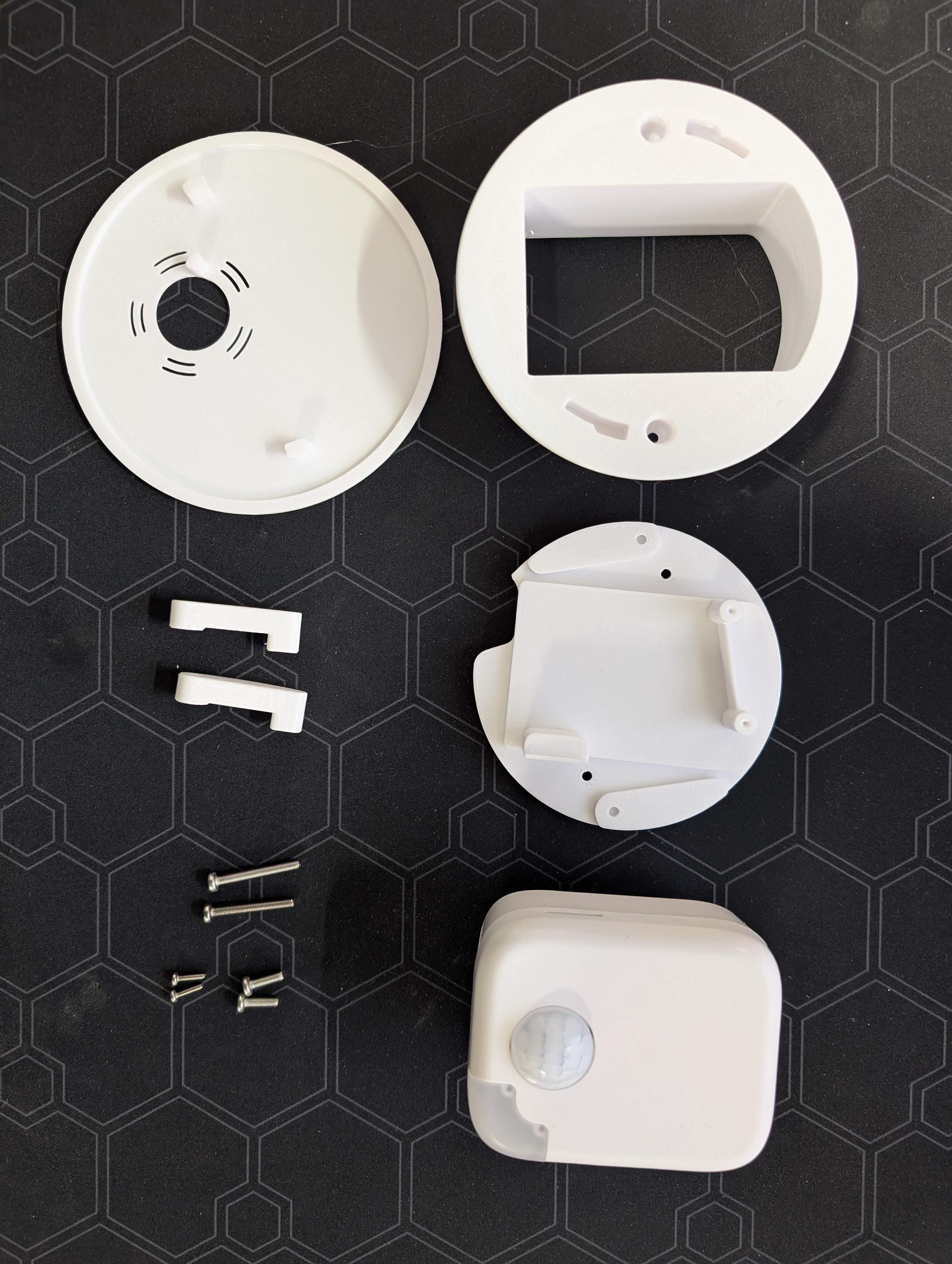
First, take the rear section, and the main Pro PCB:
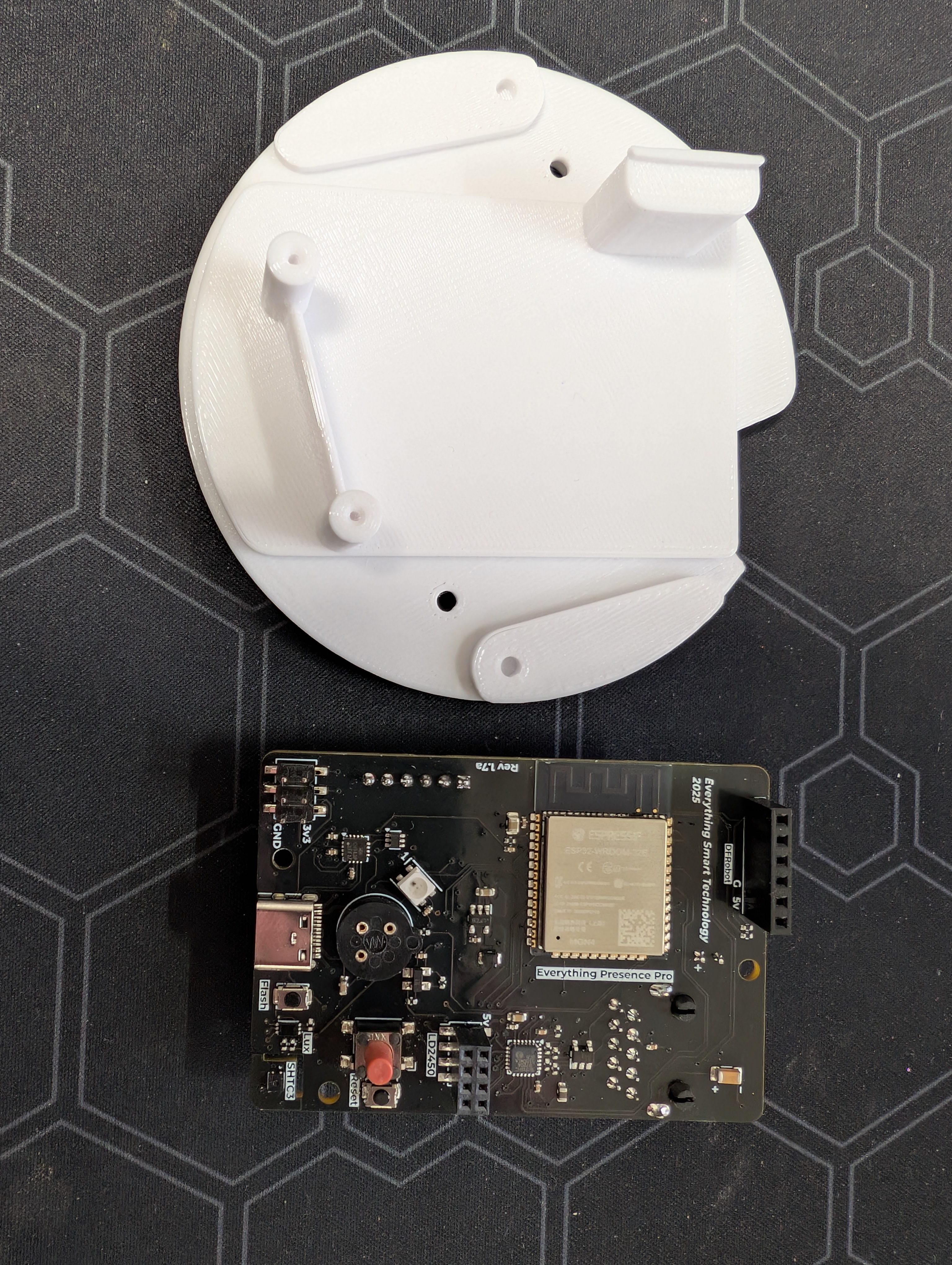
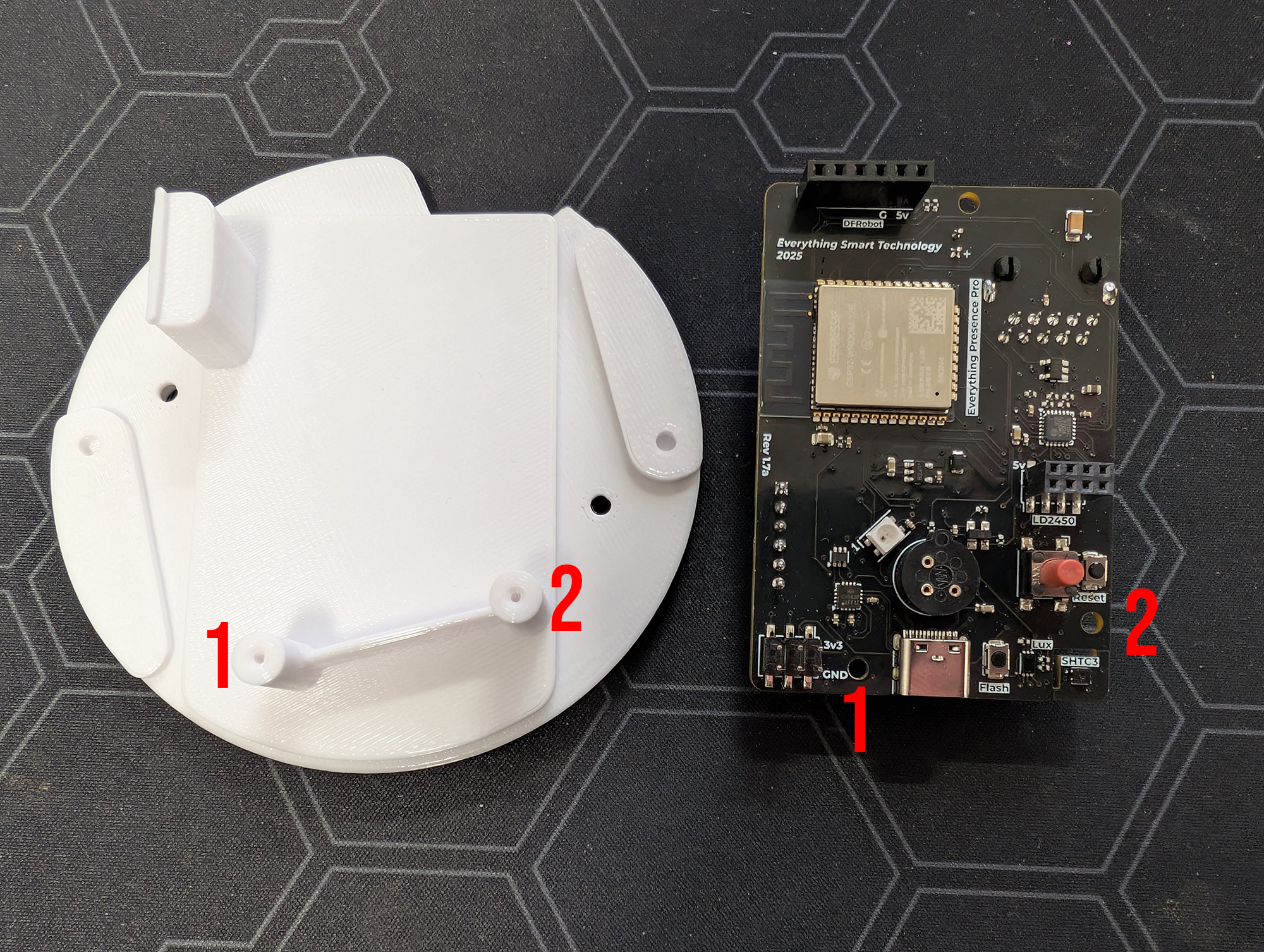
Identify the screw holes on the rear section and on the PCB:
Place the PCB ontop of the stand-offs. Note the “guide” is at the left hand side":
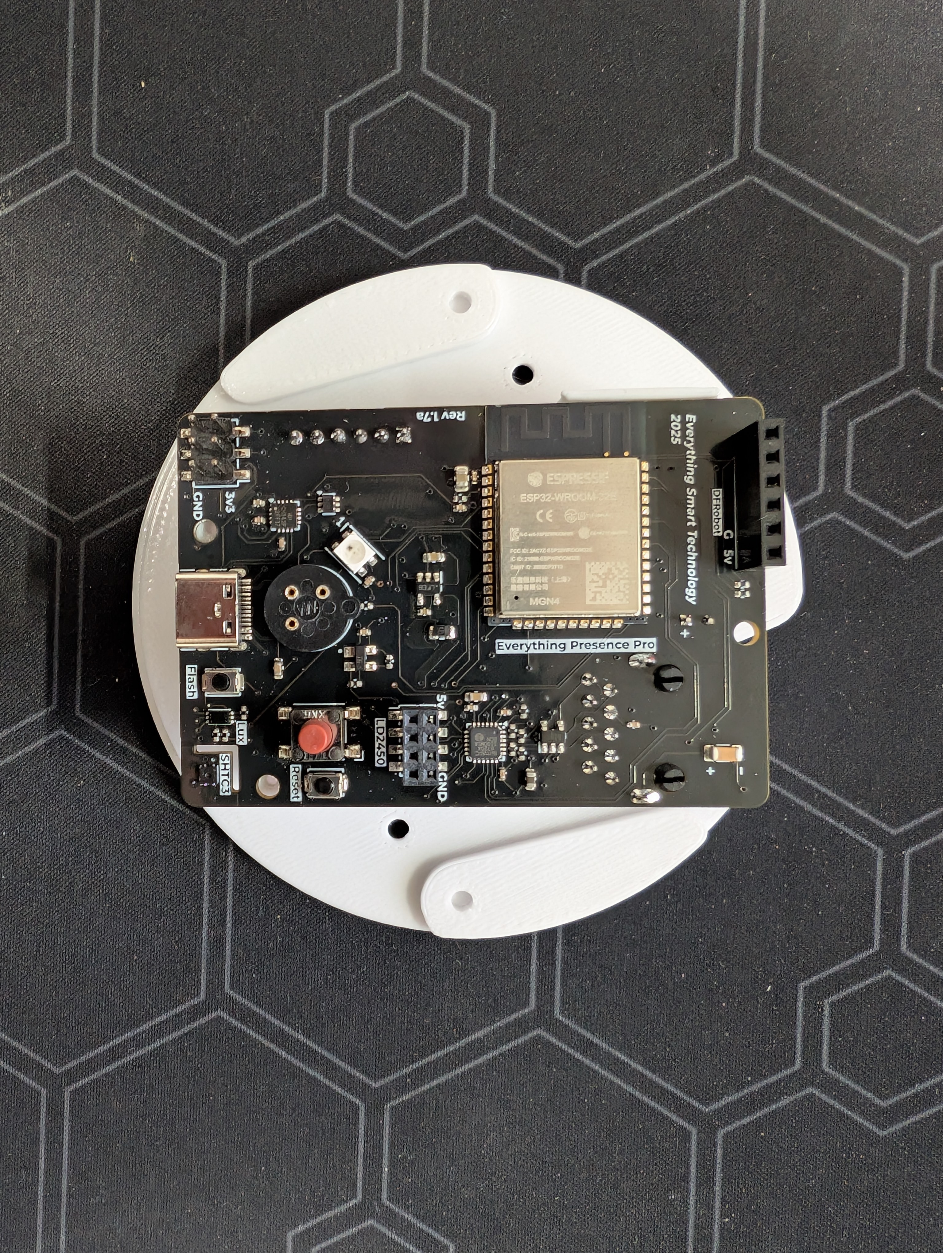
Using the little screws (M2x8), screw the PCB into the standoffs
Warning
Do NOT over tighten, or permanent damage can be caused to the PCB. These screws do not need to be extremely tight, just enough to hold it securely.
WarningNo really, do not over tighten.
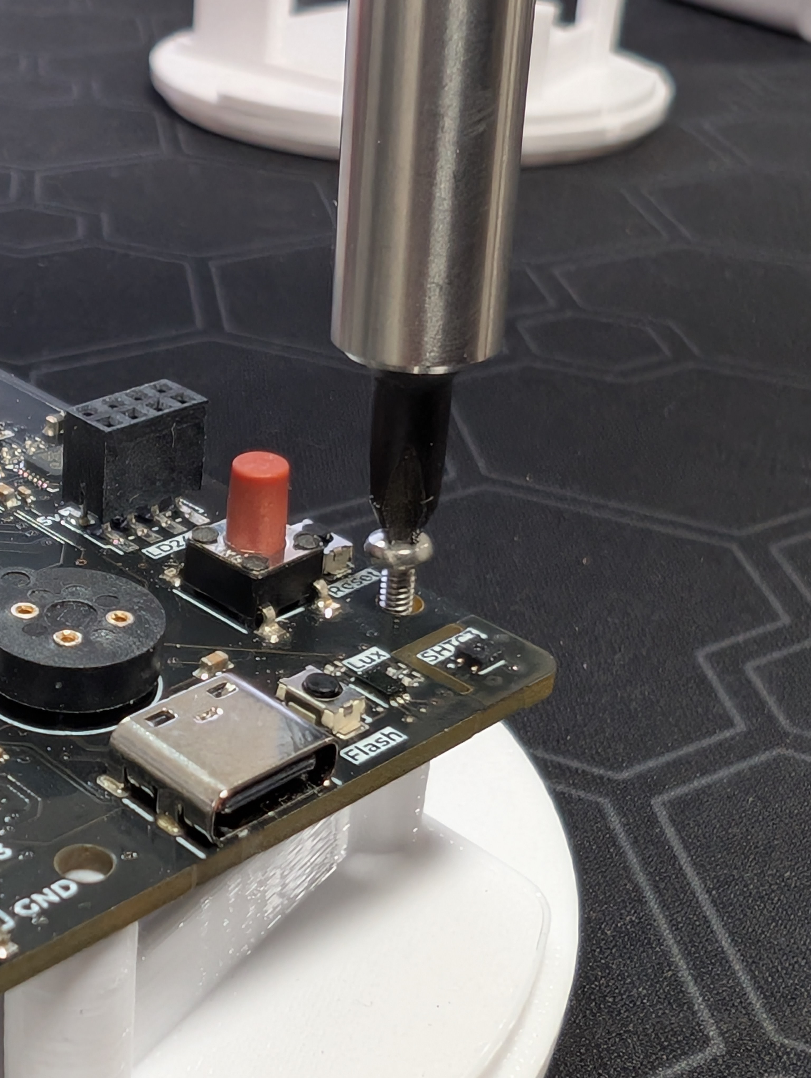
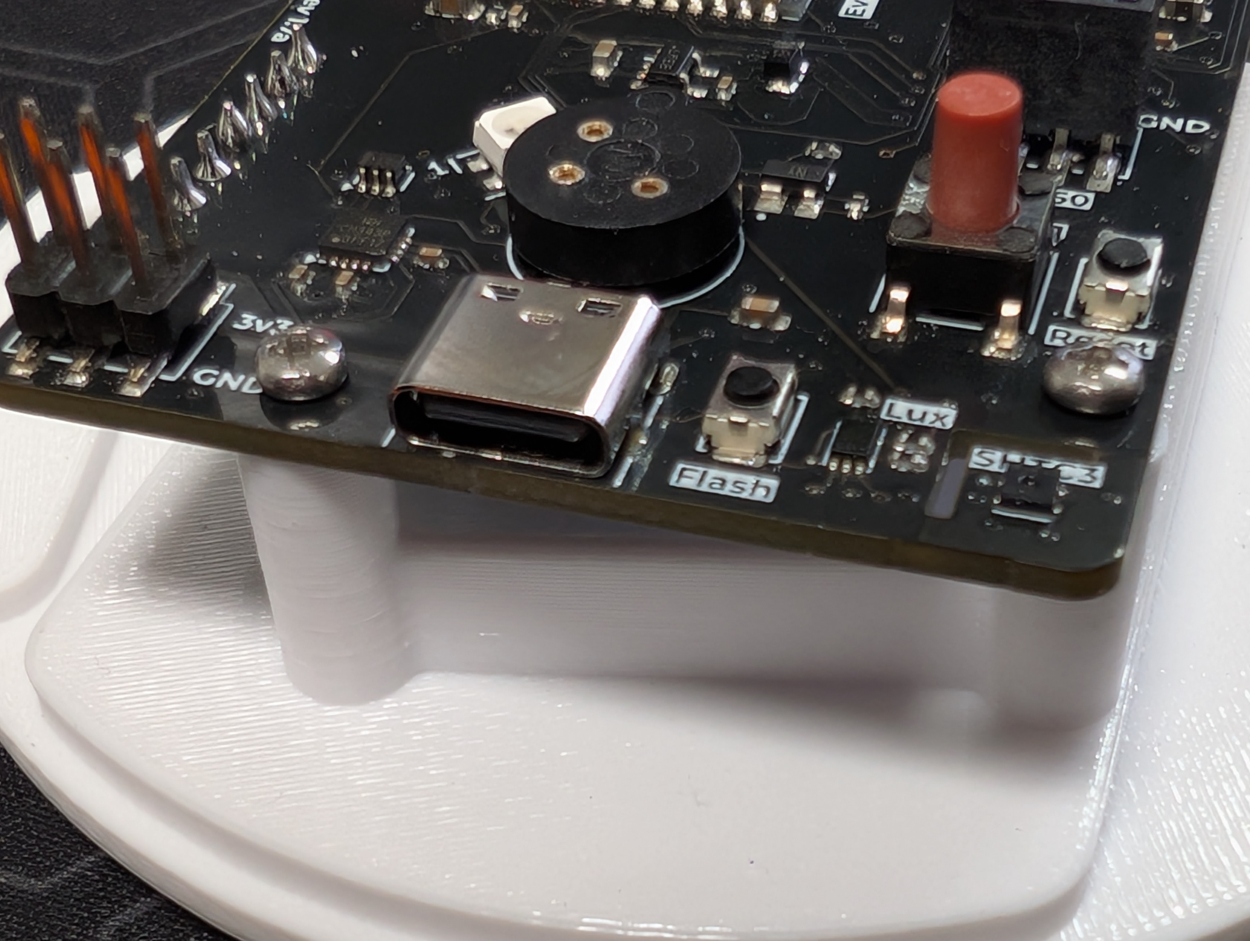
Warning
Once the the screw head touches the top of the PCB, do not keep tightening.
With both screws in, we can now attach the rear section to the middle section. Identify the ethernet cut-outs on both sides:
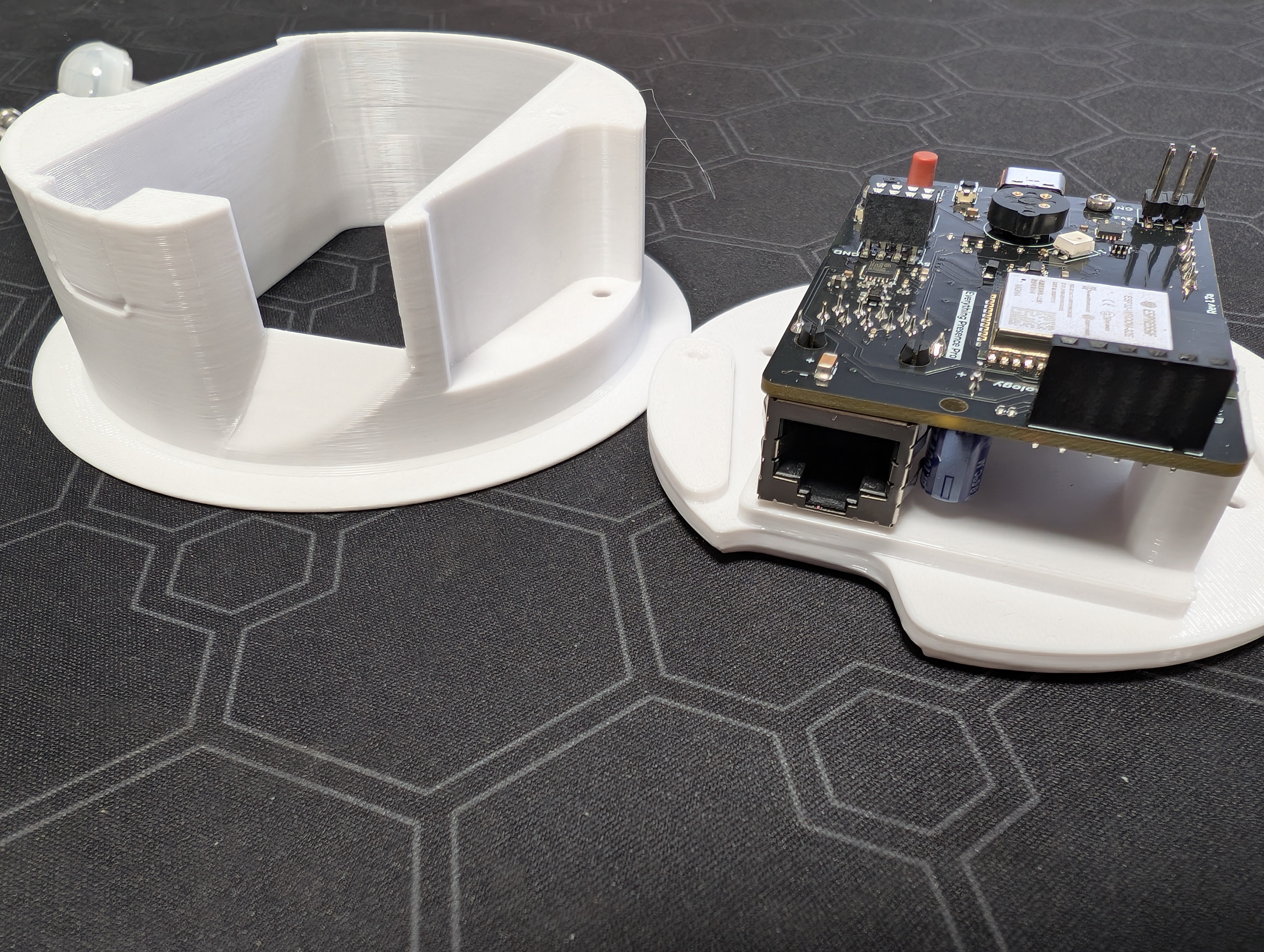
And slip the middle cover over the PCB to sit snugly on the rear section:
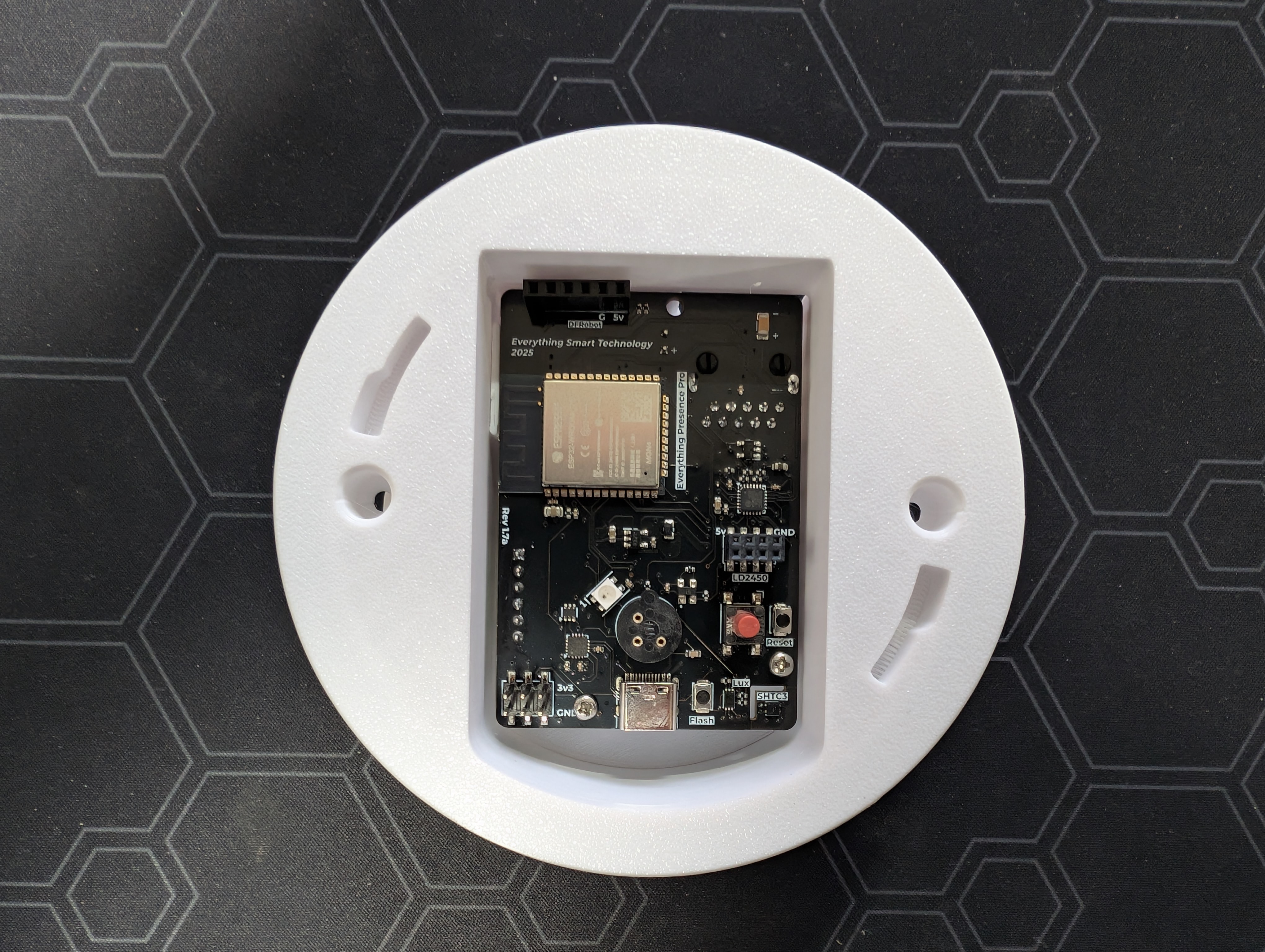
Flip it over 180 degrees and grab the middle screws (2 x M3x10):
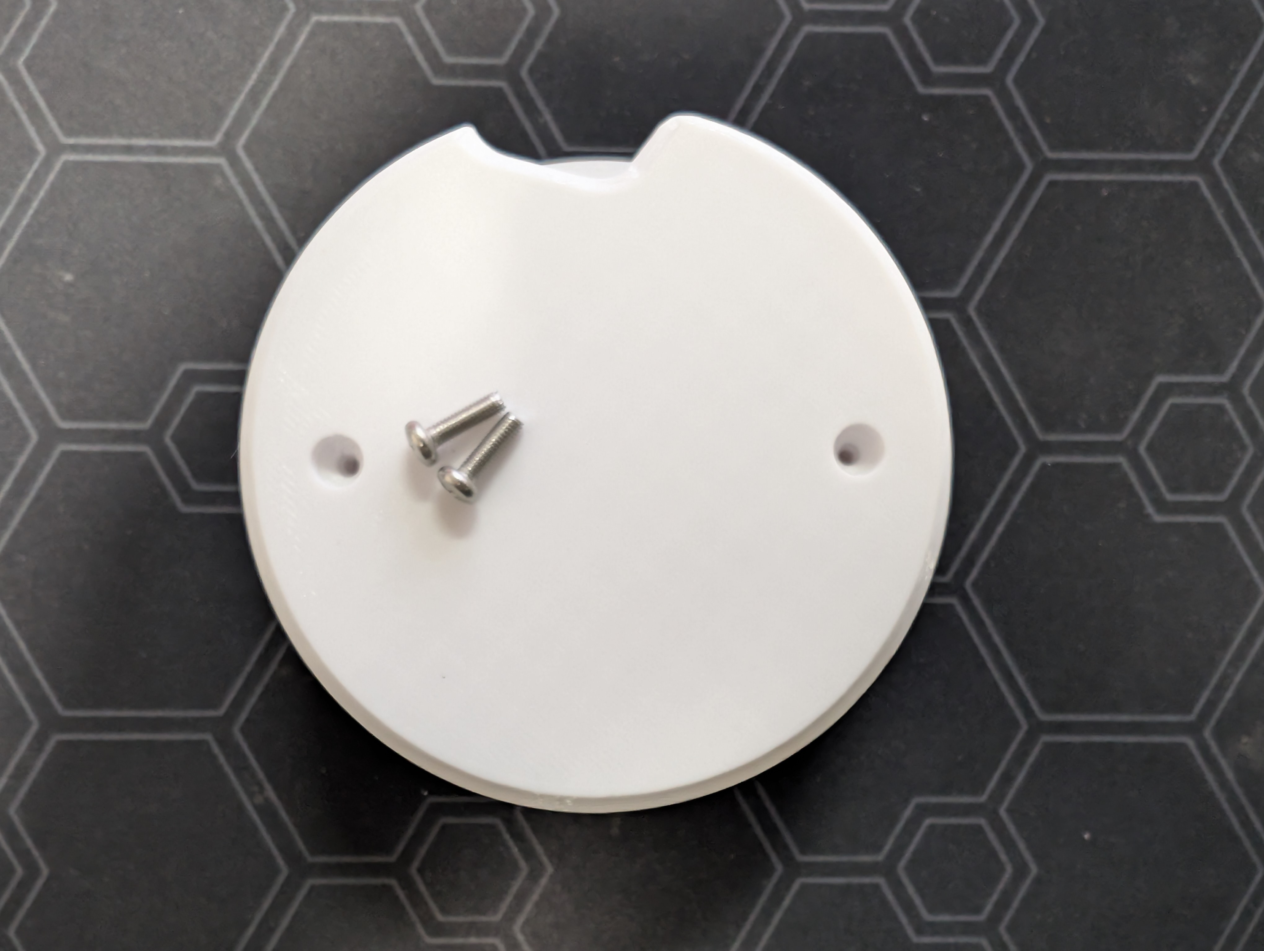
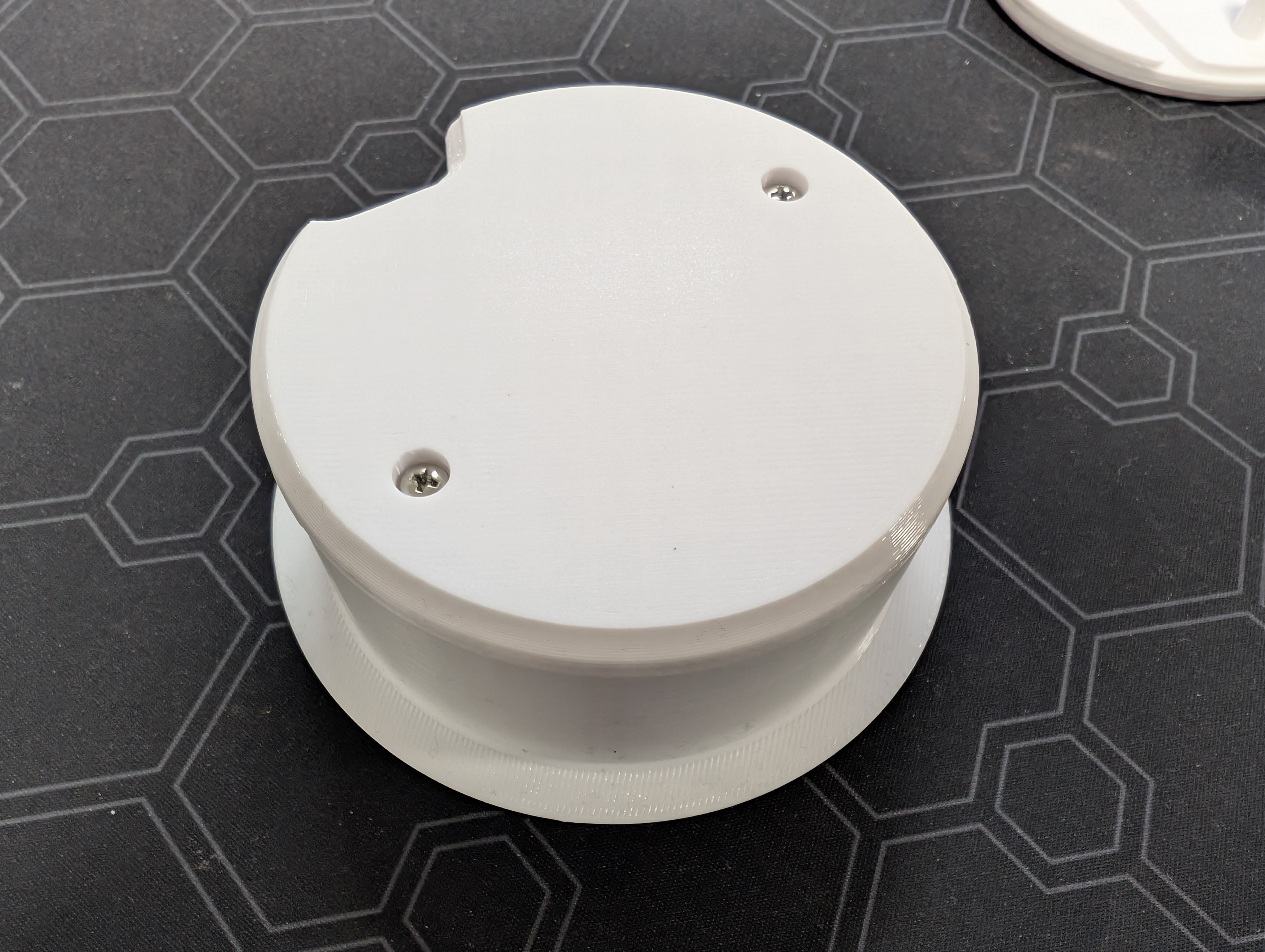
And screw the rear section into the middle section:
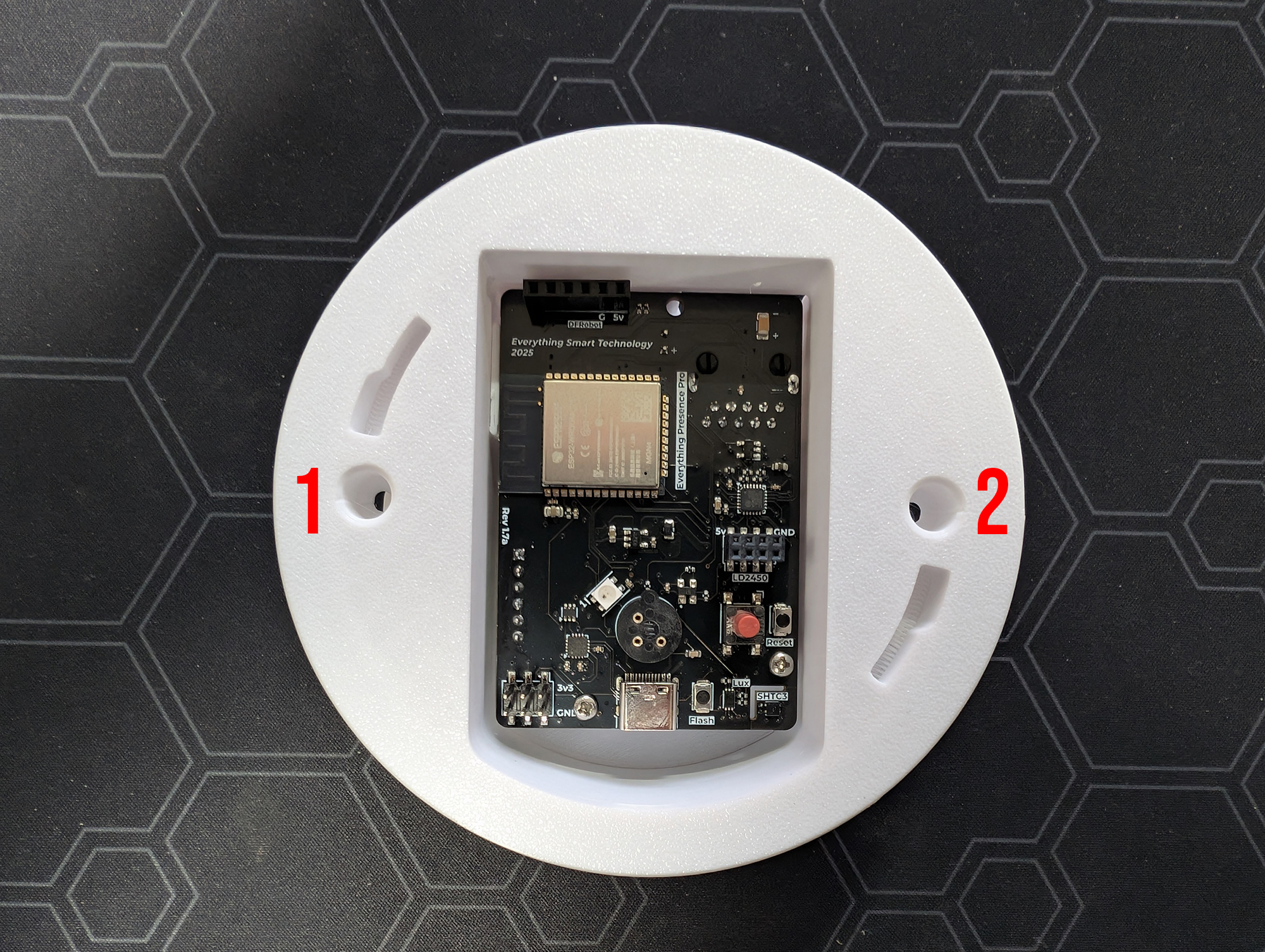
Next, get the wings and the big screws (M3x25). Turn the assembly over so that the PCB is face up again. Identify the screw holes for the wings:
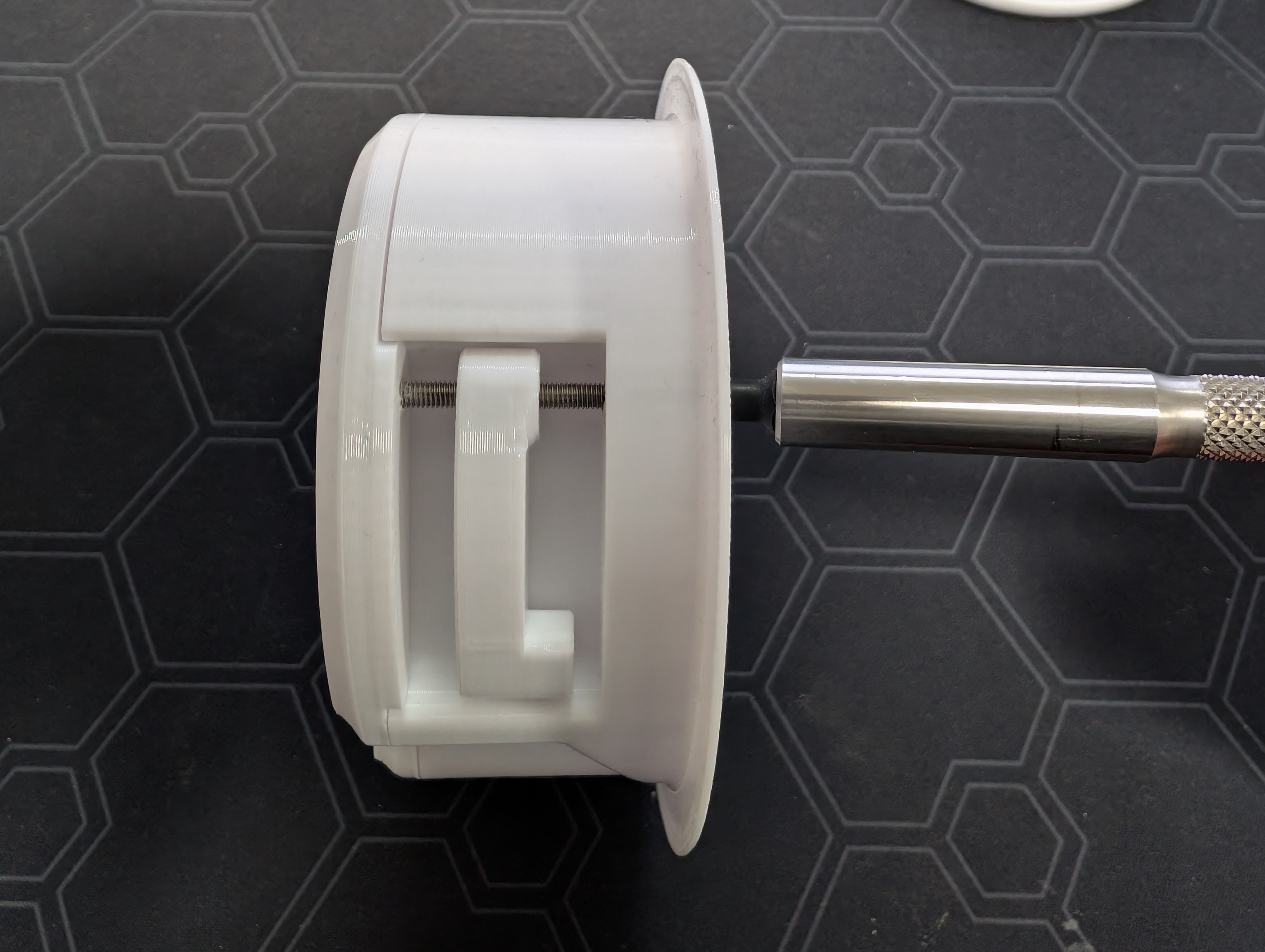
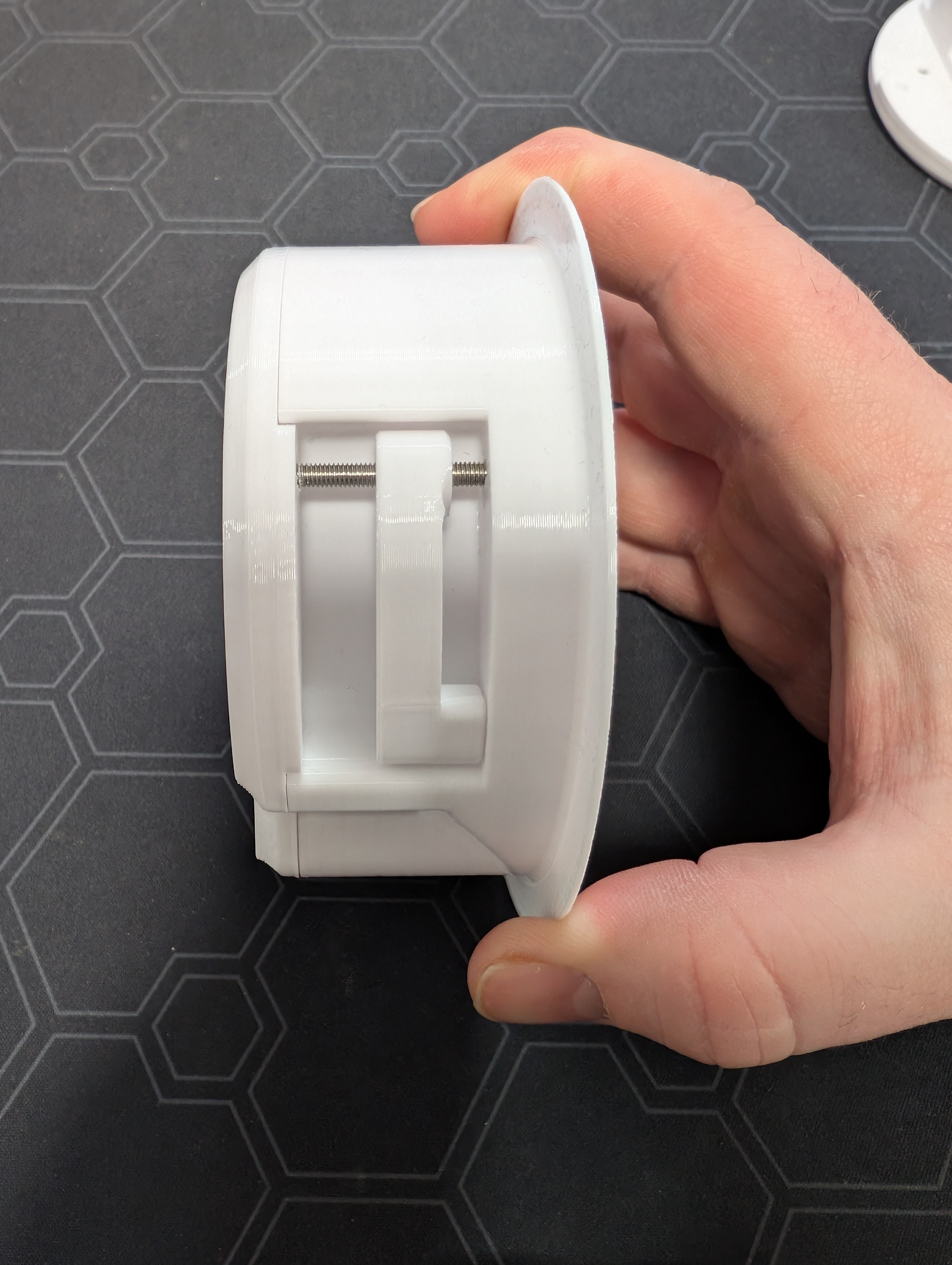
Placing the wings in their groove on the side (pay attention to orientation), start screwing a big screw through the hole and into the wing:
Tip
Hold the wing flush to ensure that the screw goes in straight and not at an angle. Allow the wing to move down the screw and towards the front.
Keep screwing until the wing is at the bottom, while still fully inside of the cut-out
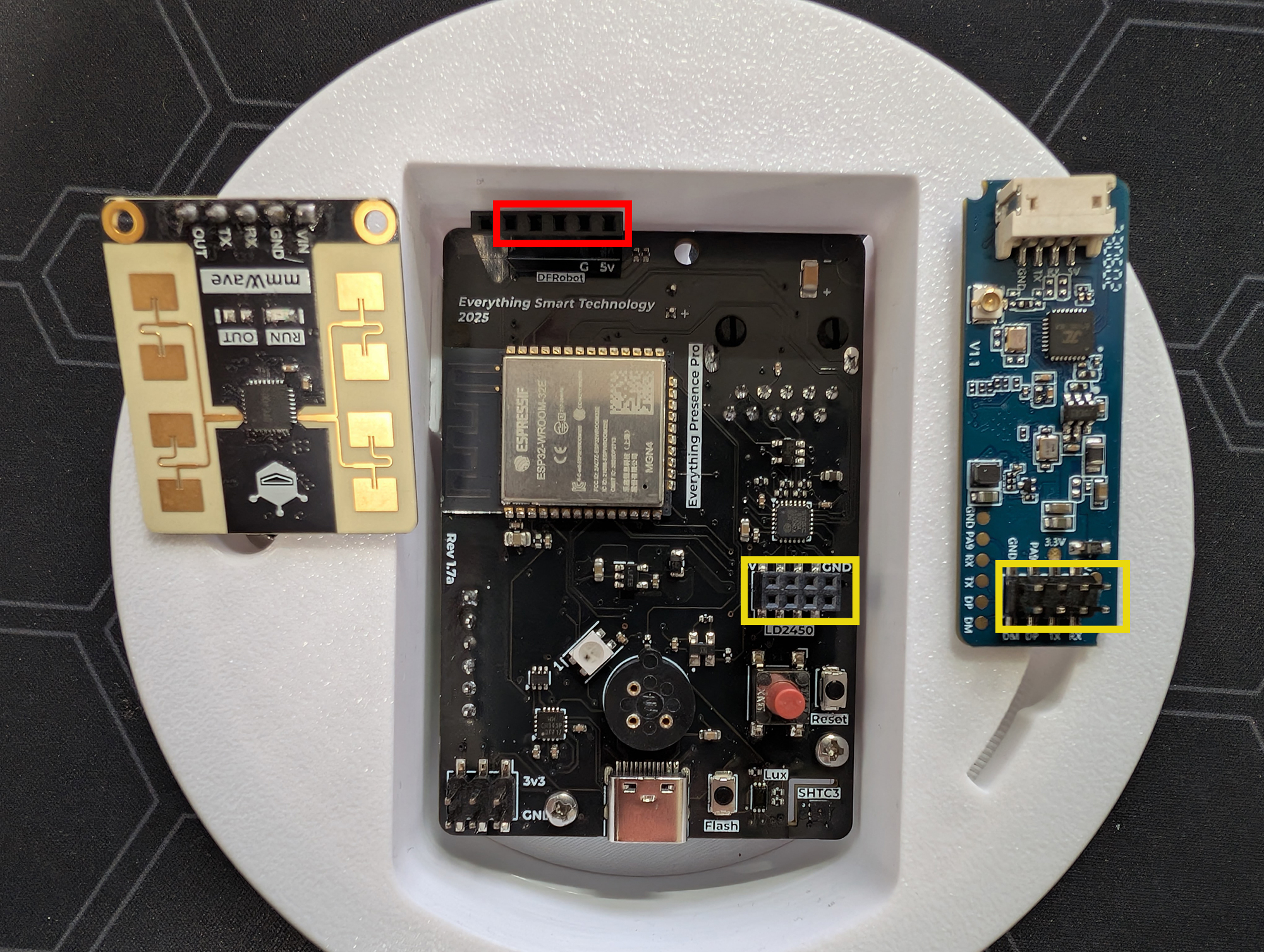
Then we can install the sensors back into the Pro PCB. Start with the mmwave sensors, ensuring to line up the pins in their respective sockets.
Warning
Take care to line up the “VIN” pin on the DFRobot mmWave (the yellow one) with the “5v” pin marked on the main Pro PCB.
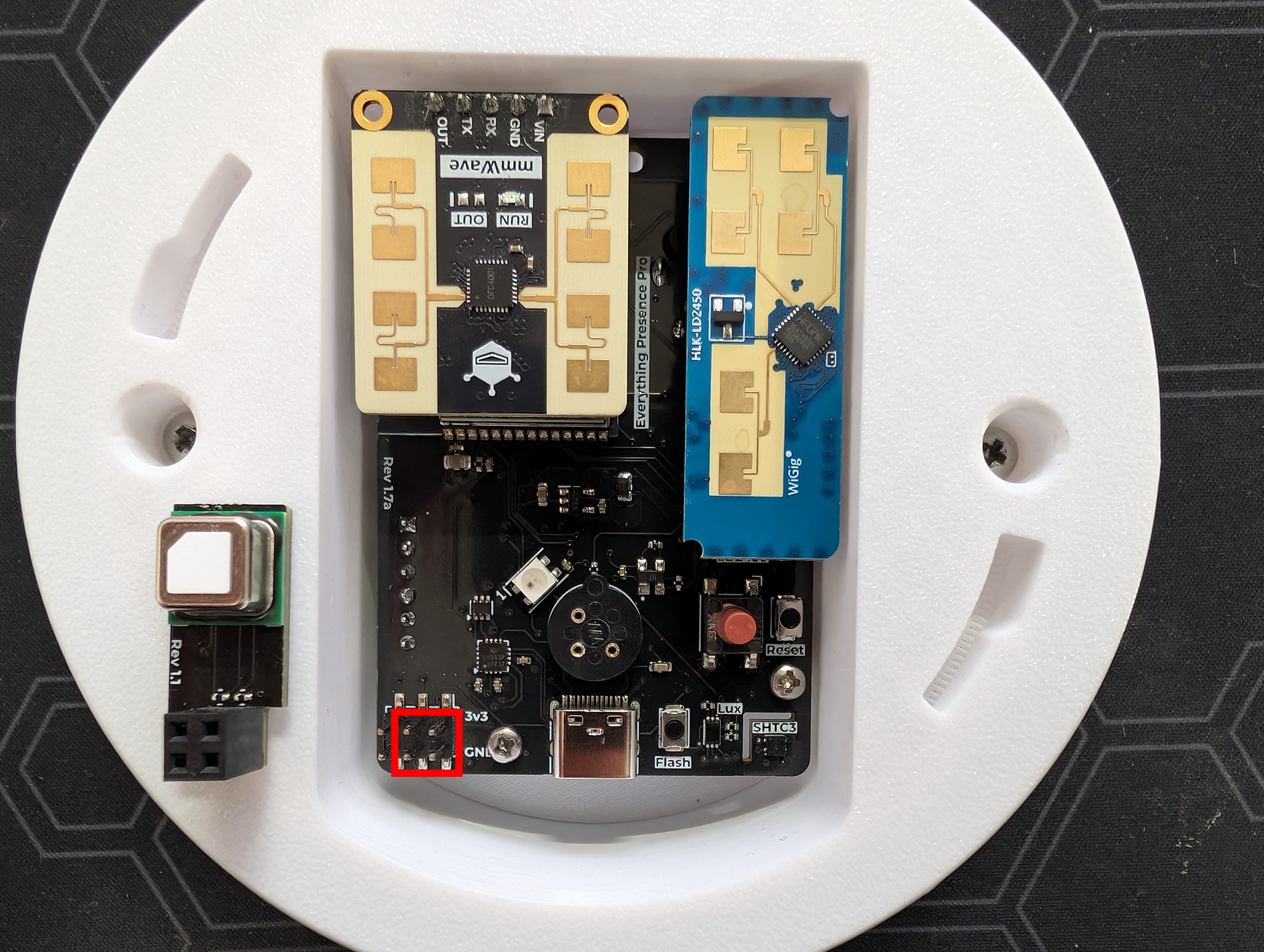
If you have the optional CO2 module, now is a good time to insert that:
Warning
Take care to line up the 3v3 and GND pin on the CO2 sensor with the 3v3 and GND pins on the main Pro PCB
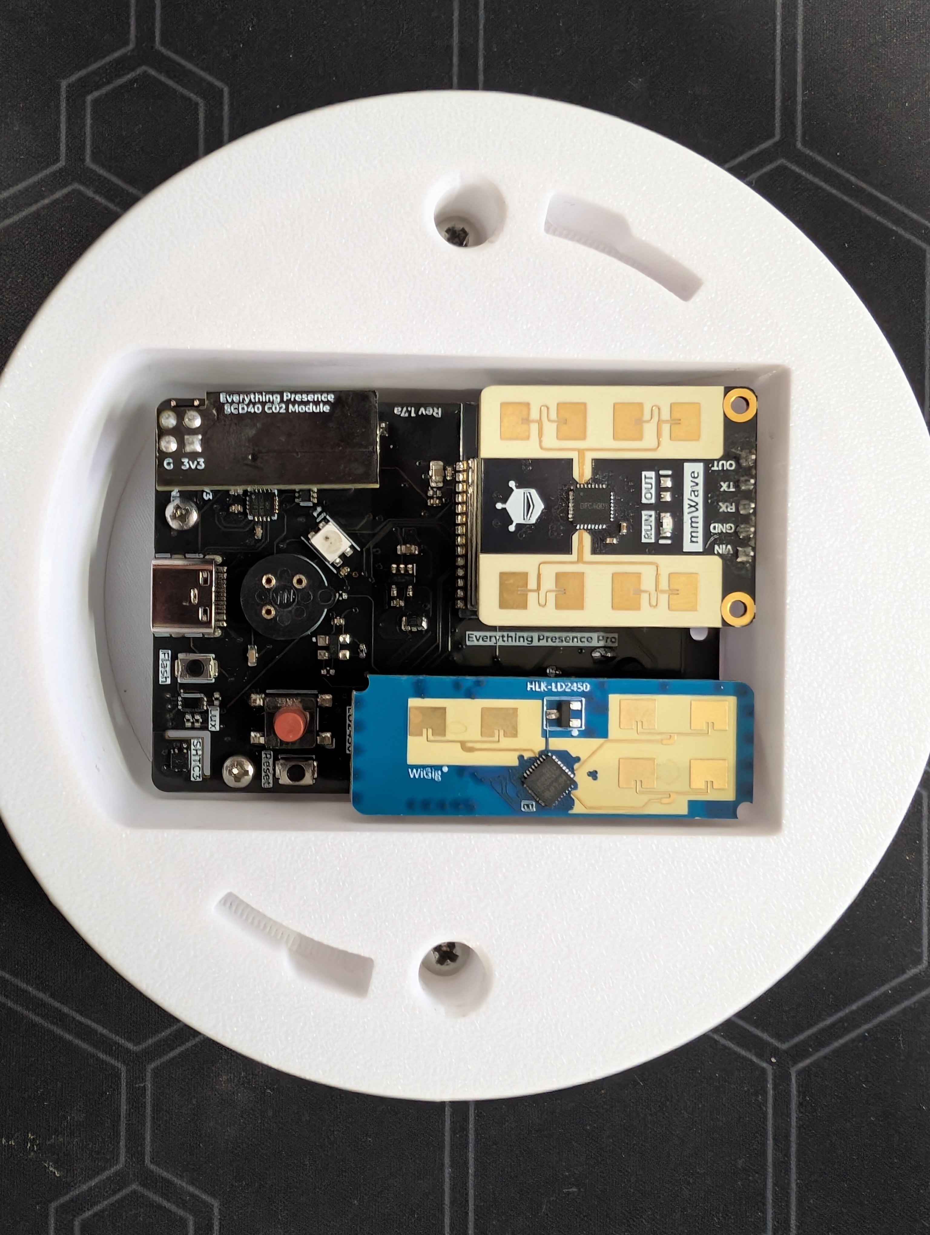
Next take the front section and insert the locating pins into the locating holes on the middle section. Then twist clockwise into place.
Tip
Due to the 3D printed nature, the first time you twist the front section on, it may be quite stiff, but should loosen off after a few tries.
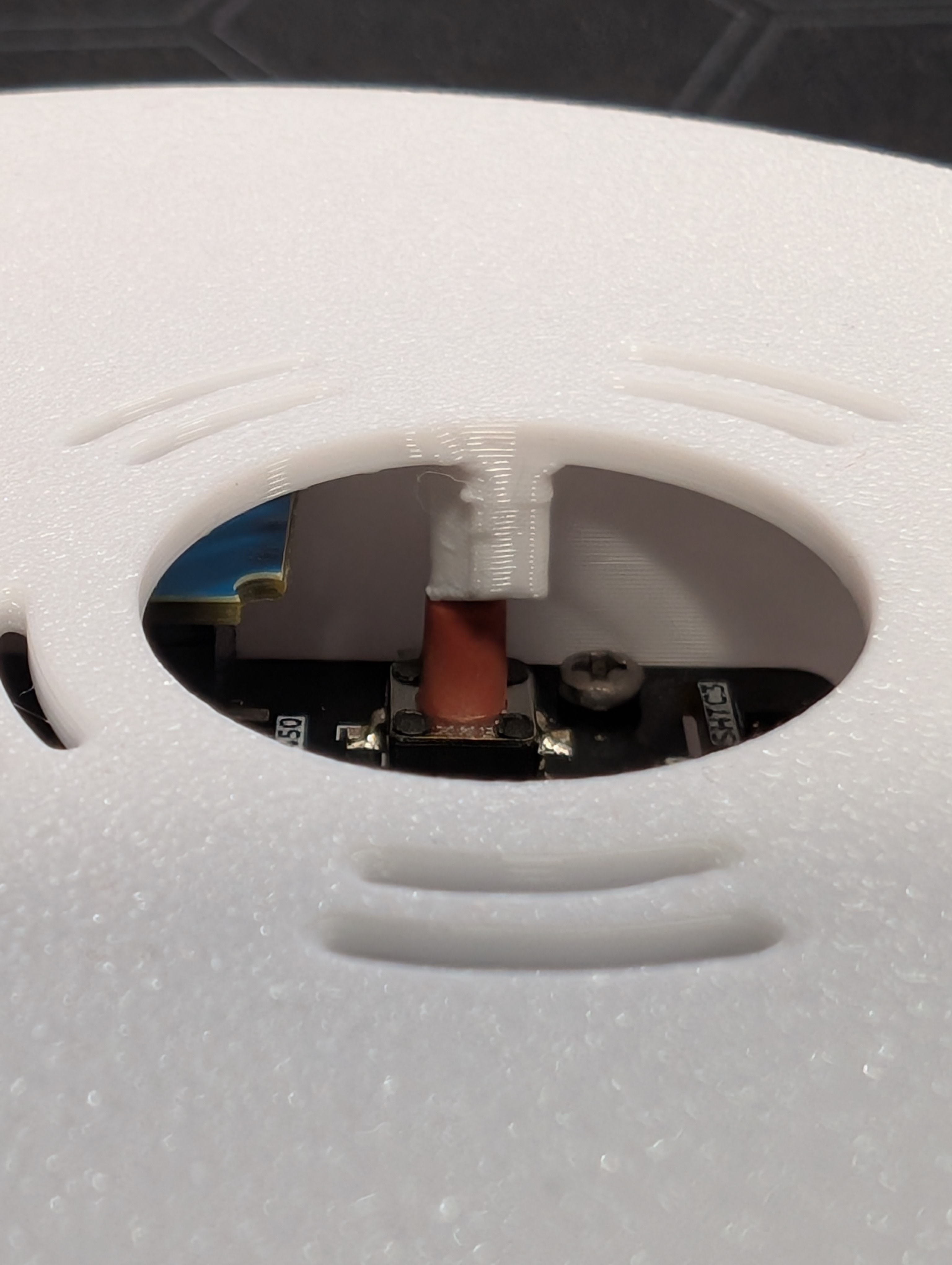
WarningThe first time you put the front cover on, look through the hole to ensure that the tamper switch peg on the case does not bend the tamper switch over. It will be snug, and may need a little assistant to get over the top of the tamper switch.
The tamper switch can be seen through the hole here:
Finally, we can place in the PIR sensor:
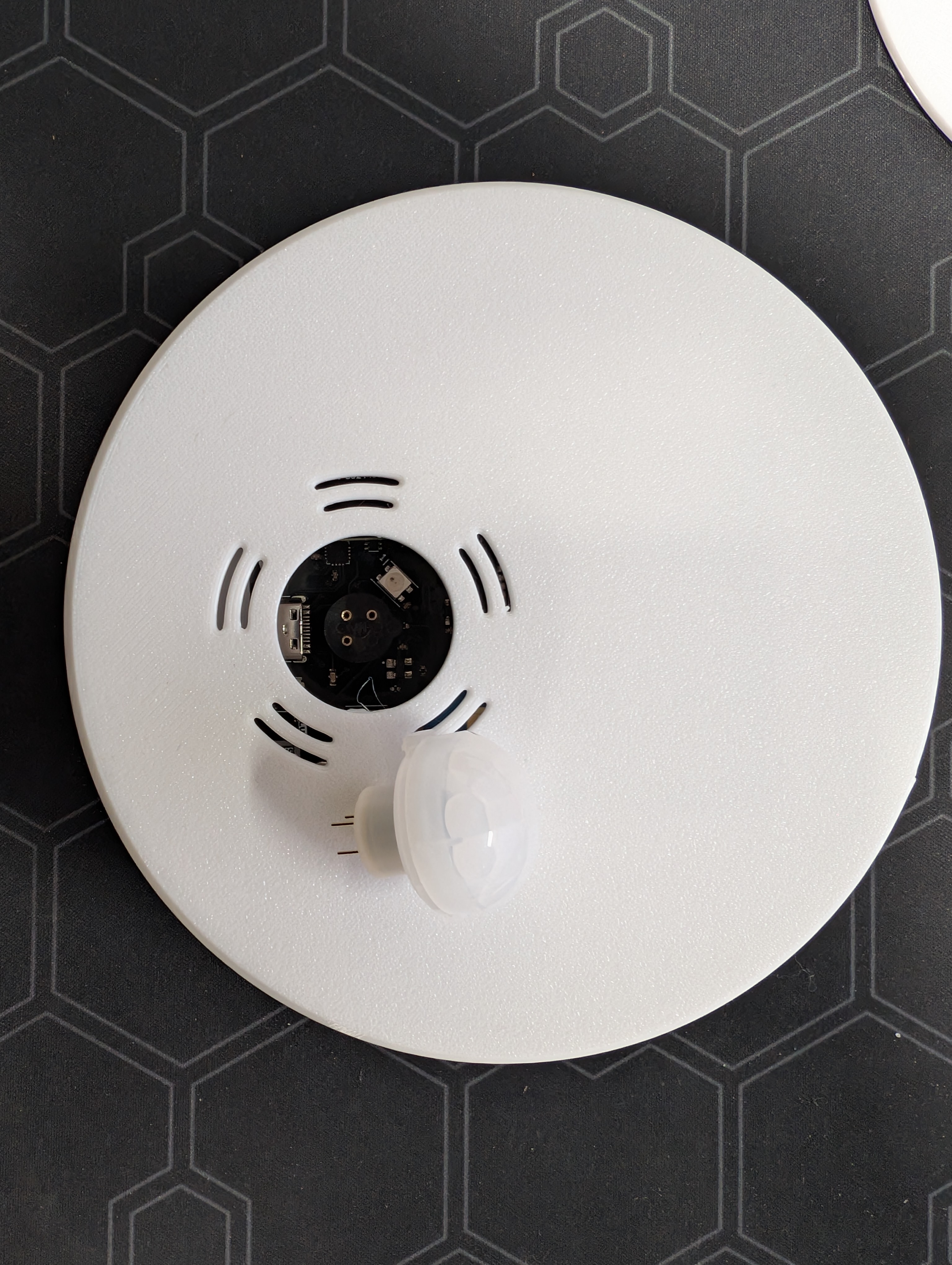
Tip
This is fiddley but with patience, it will line up and go in
WarningAvoid putting the PIR in before putting the front section on, as it can bend the PIR legs
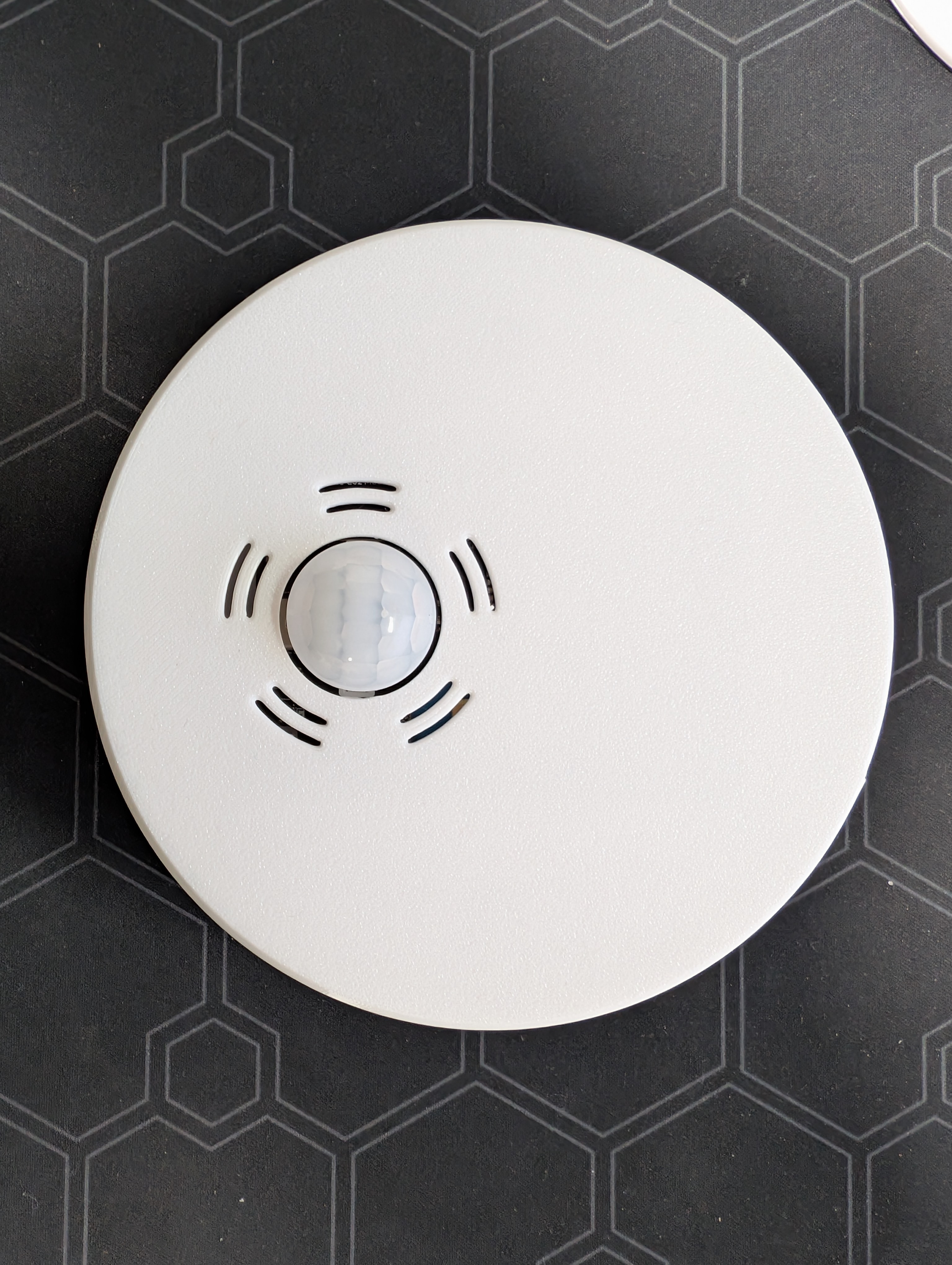
The Ceiling Mount is now ready to be installed!
Installing into a ceiling
Some things are easier to demonstrate on video, so I recommend checking out StockPot’s (designer of the Ceiling Mount case!) video where he shows how to install into Plasterboard/Drywall:
https://www.youtube.com/watch?v=4TA%5FFH-euSU&pp=0gcJCYcKAYcqIYzv