Alarm Panel Integration
Explore alarm panel integration for Everything Presence Pro and review the connections and setup described in the guide.
The Everything Presence Pro includes a solid-state relay output with screw terminals, making it easy to integrate with traditional alarm panels and security systems.
Relay Specifications
| Specification | Value |
|---|---|
| Type | Solid-state relay |
| Configuration | Normally Open (NO) by default. Normally Closed (NC) also available — configurable in Home Assistant via the Relay Contact Type select entity. |
| Terminals | Screw terminal block |
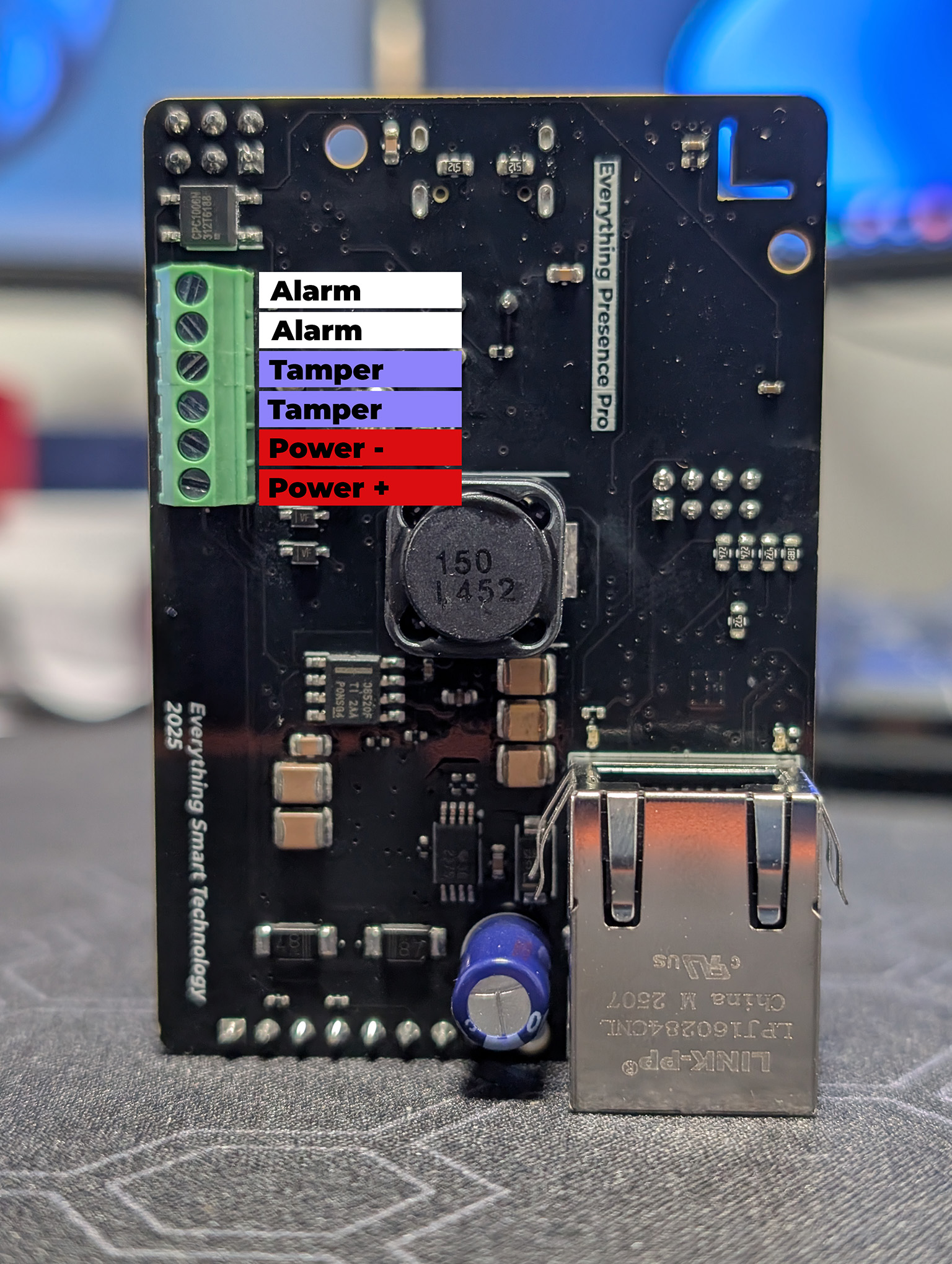
Warning
Image coming soon!
Basic Connection
There are a few different ways that the EP Pro can interface to an alarm panel. The interface method is determined by the alarm panel; some panels can support more than one method so it's important to consult the alarm panel documentation.
There are 2 main methods that are common in the vast majority of panels on the market, these are:
Closed Circuit Loop (CCL)
With the CCL method each circuit needs 2 cable cores. Two for the alarm circuit, 2 for the tamper circuit as well as 2 for the power supply (if needed).
Fully Supervised Loop (FSL)
With the FSL method only 2 cores, plus some suitable resistors are needed. Again 2 cores will be required for the power supply if needed. The resistor values are determined by the alarm panel.
As mentioned above, some panels support both methods. Given the option, users should choose FSL where possible as it is a more secure method.
Alarm panels that support FSL connection essentially measure the resistance of the loop to determine its status.
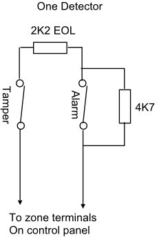
Consider the diagram to the right. The control panel will measure the following resistance values and can thus differentiate the type of alarm.
Healthy / No Alarm – 2K2
Alarm – 6K9 (2K2 + 4K7)
Tamper – Infinity
Important
Only 1 EOL resistor is needed per loop even if there are 2 or more detectors on a single loop.
As the name suggests, the EOL resistor must be fitted at the remote end of the loop. If the EOL resistor is fitted at the panel end, the loop will still function but the system can be easily defeated.
Info
More details coming soon
Wiring Diagrams
Warning
Image coming soon!
Configuring the Relay
Trigger Modes
In Home Assistant, find the Relay Trigger Mode select entity to configure automatic triggering:
| Mode | Behaviour |
|---|---|
| Disabled | Relay only responds to manual control |
| Motion Only | Relay activates when PIR detects motion |
| Presence Only | Relay activates when occupancy is detected |
| Motion or Presence | Relay activates on either trigger |
Manual Control
The Relay Output switch entity allows manual on/off control, useful for:
- Testing the connection
- Custom automations
- Overriding automatic behaviour
Troubleshooting
Relay Not Activating
- Check Relay Trigger Mode is not set to "Disabled"
- Verify presence/motion is being detected (check binary sensors)
- Test with manual control via Relay Output switch
- Check wiring connections at screw terminals
False Alarms
- Reduce detection sensitivity
- Add exclusion zones for problem areas
- Increase timeout values
- Consider using "Presence Only" mode instead of "Motion"
Alarm Panel Not Seeing Zone
- Verify wiring polarity
- Check EOL resistor if required
- Test relay with multimeter (should show continuity when activated)
- Ensure alarm zone is properly programmed
Using Home Assistant Automations Instead
For more flexibility, you can bypass the built-in relay trigger modes and use Home Assistant automations:
automation:
  - alias: "Pro to Alarm Panel"
    trigger:
      - platform: state
        entity_id: binary_sensor.pro_occupancy
        to: "on"
    condition:
      - condition: state
        entity_id: alarm_control_panel.home_alarm
        state: "armed_away"
    action:
      - service: switch.turn_on
        target:
          entity_id: switch.pro_relay_output
This gives you control over:
- Which sensors trigger the relay
- Time-based conditions
- Alarm state awareness
- Custom delays and logic